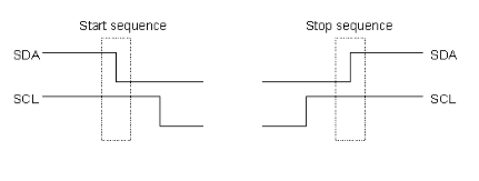
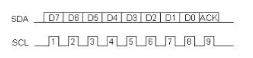
The I2C Physical Protocol
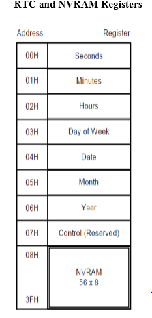
I2C Device Addressing

Notes:
/*  Name     : main.c
 *  Purpose  : Source code for RTC-DS1307 Interfacing with AT89C52.
 *  Author   : Gemicates
 *  Date     : 2014-03-05
 *  Website  : www.gemicates.org
 *  Revision : None
 */

#include "Includes.h"

// Main function
void main()
{
	InitLCD();	                            			// Initialize LCD
	InitI2C();	                            			// Initialize i2c pins

									// Set initial time
	Set_DS1307_RTC_Time(PM_Time, 8, 8, 8);				// Set time 08:32:59 AM

									// Set initial date
	Set_DS1307_RTC_Date(4, 03, 91, Monday);				// Set 04-03-1991 @ Monday

	while(1)
	{
									// Display RTC time on first line of LCD
		DisplayTimeToLCD(Get_DS1307_RTC_Time());

									// Display RTC date on second line of LCD
		DisplayDateOnLCD(Get_DS1307_RTC_Date());

		delay(65000);	                    			// Roughly about 1 second delay
	}
}
#include "Includes.h"

void ToggleEpinOfLCD(void)
{
	E = 1;                                   	                        // Give a pulse on E pin
	__delay_us(E_Delay);                    	                        // so that LCD can latch the
	E = 0;                                 		                        // data from data bus
	__delay_us(E_Delay);
}

void WriteDataToLCD(char t)
{
   RS = 1;                                		                        // This is data

   P2 &= 0x0F;		                     	 	                        // Make P2.4 to P2.7 zero
   P2 |= (t&0xF0);                        		                        // Write Upper nibble of data
   ToggleEpinOfLCD();                     		                        // Toggle E pin to send data

   P2 &= 0x0F;		                     		                        // Make P2.4 to P2.7 zero
   P2 |= ((t<<4)&0xF0);                  		                        // Write Lower nibble of data
   ToggleEpinOfLCD();                    		                        // Toggle E pin to send data
}


void WriteCommandToLCD(int z)
{
   RS = 0;                               		                        // This is command

   P2 &= 0x0F;                          		                        // Make P2.4 to P2.7 zero
   P2 |= (z&0xF0);                      		                        // Write Upper nibble of data
   ToggleEpinOfLCD();                   		                        // Toggle E pin to send data

   P2 &= 0x0F;		                    		                        // Make P2.4 to P2.7 zero
   P2 |= ((z<<4)&0xF0);                 		                        // Write Lower nibble of data
   ToggleEpinOfLCD();                  			                        // Toggle E pin to send data
}

void InitLCD(void)
{
	RS = 0;		 	                  	                                // Make pin zero
	E  = 0;			                  	                                // Make Pin zero

  ///////////// Reset process from datasheet /////////
     __delay_us(15000);

	 P2 &= 0x0F;		             		                            // Make P2.4 to P2.7 zero
	 P2 |= 0x30;    	            		                            // Write 0x3
     ToggleEpinOfLCD();             			                        // Toggle E pin to send data

     __delay_us(4500);

	 P2 &= 0x0F;		            		                            // Make P2.4 to P2.7 zero
	 P2 |= 0x30;    	           		                                // Write 0x3
     ToggleEpinOfLCD();           			                            // Toggle E pin to send data

     __delay_us(300);

	 P2 &= 0x0F;		         		                                // Make P2.4 to P2.7 zero
	 P2 |= 0x30;    	         		                                // Write 0x3
     ToggleEpinOfLCD();          			                            // Toggle E pin to send data

     __delay_us(650);

	 P2 &= 0x0F;		         		                                // Make P2.4 to P2.7 zero
	 P2 |= 0x20;    	         		                                // Write 0x2
     ToggleEpinOfLCD();          			                            // Toggle E pin to send data

	 __delay_us(650);

  /////////////////////////////////////////////////////
   WriteCommandToLCD(0x28);     			                            //function set
   WriteCommandToLCD(0x0c);     			                            //display on,cursor off,blink off
   WriteCommandToLCD(0x01);     			                            //clear display
   WriteCommandToLCD(0x06);     			                            //entry mode, set increment
}


void ClearLCDScreen(void)       			                            // Clear the Screen and return cursor to zero position
{
	WriteCommandToLCD(0x01);    			                            // Clear the screen
	__delay_us(2000);           			                            // Delay for cursor to return at zero position
}


void WriteStringToLCD(const char *s)
{
	while(*s)
		WriteDataToLCD(*s++);
}


void DisplayTimeToLCD( unsigned char* pTimeArray )                      // Displays time in HH:MM:SS AM/PM format
{
	ClearLCDScreen();                                                   // Move cursor to zero location and clear screen

							                                            // Display Hour
	WriteDataToLCD( (pTimeArray[2]/10)+0x30 );
	WriteDataToLCD( (pTimeArray[2]%10)+0x30 );

							                                            //Display ':'
	WriteDataToLCD(':');

							                                            //Display Minutes
	WriteDataToLCD( (pTimeArray[1]/10)+0x30 );
	WriteDataToLCD( (pTimeArray[1]%10)+0x30 );

							                                            //Display ':'
	WriteDataToLCD(':');

							                                            //Display Seconds
	WriteDataToLCD( (pTimeArray[0]/10)+0x30 );
	WriteDataToLCD( (pTimeArray[0]%10)+0x30 );

							                                            //Display Space
	WriteDataToLCD(' ');

							                                            // Display mode
	switch(pTimeArray[3])
	{
	case AM_Time:	WriteStringToLCD("AM");	break;
	case PM_Time:	WriteStringToLCD("PM");	break;

	default: WriteDataToLCD('H');	break;
	}
}


void DisplayDateOnLCD( unsigned char* pDateArray )                      // Displays Date in DD:MM:YY @ Day format
{
	WriteCommandToLCD(0xc0);                                            // Move cursor to second line

							                                            // Display Date
	WriteDataToLCD( (pDateArray[1]/10)+0x30 );
	WriteDataToLCD( (pDateArray[1]%10)+0x30 );

							                                            //Display '/'
	WriteDataToLCD('/');

							                                            //Display Month
	WriteDataToLCD( (pDateArray[2]/10)+0x30 );
	WriteDataToLCD( (pDateArray[2]%10)+0x30 );

							                                            //Display '/'
	WriteDataToLCD('/');

							                                            //Display Year
	WriteDataToLCD( (pDateArray[3]/10)+0x30 );
	WriteDataToLCD( (pDateArray[3]%10)+0x30 );

							                                            //Display Space
	WriteDataToLCD(' ');

							                                            // Display Day
	switch(pDateArray[0])
	{
	case Monday:	WriteStringToLCD("MON");	break;
	case Tuesday:	WriteStringToLCD("TUE");	break;
	case Wednesday:	WriteStringToLCD("WED");	break;
	case Thursday:	WriteStringToLCD("THU");	break;
	case Friday:	WriteStringToLCD("FRI");	break;
	case Saturday:	WriteStringToLCD("SAT");	break;
	case Sunday:	WriteStringToLCD("SUN");	break;

	default: WriteStringToLCD("???");	break;
	}
}
#include "Includes.h"

// Function Purpose: Produce approximate delay in given uSecs.
void __delay_us(unsigned int d)
{
   unsigned int i, limit;
   limit = d/15;

   for(i=0;i<limit;i++);
}


// Function Purpose: Set initial values of SCK and SDA pins
void InitI2C(void)
{
	// Make SDA and SCK pins input initially
	SDA = 1;
	SCK = 1;
}


// Function Purpose: I2C_Start sends start bit sequence
void I2C_Start(void)
{
	Set_SCK_High;				                       // Make SCK pin high
	Set_SDA_High;				                       // Make SDA pin High
	__delay_us(HalfBitDelay);	                               // Half bit delay
	Set_SDA_Low;				                       // Make SDA Low
	__delay_us(HalfBitDelay);	                               // Half bit delay
}


// Function Purpose: I2C_ReStart sends start bit sequence
void I2C_ReStart(void)
{
	Set_SCK_Low;				                       // Make SCK pin low

	__delay_us(HalfBitDelay/2);	                               // Data pin should change it's value,
								       // when it is confirm that SCK is low
	Set_SDA_High;				                       // Make SDA pin High

	__delay_us(HalfBitDelay/2);	                               // 1/4 bit delay
	Set_SCK_High;				                       // Make SCK pin high
	__delay_us(HalfBitDelay/2);	                               // 1/4 bit delay
	Set_SDA_Low;				                       // Make SDA Low
	__delay_us(HalfBitDelay/2);	                               // 1/4 bit delay
}


//Function : I2C_Stop sends stop bit sequence
void I2C_Stop(void)
{
	Set_SCK_Low;				                       // Make SCK pin low

	__delay_us(HalfBitDelay/2);	                               // Data pin should change it's value,
								       // when it is confirm that SCK is low
	Set_SDA_Low;				                       // Make SDA pin low

	__delay_us(HalfBitDelay/2);	                               // 1/4 bit delay
	Set_SCK_High;				                       // Make SCK pin high
	__delay_us(HalfBitDelay/2);	                               // 1/4 bit delay
	Set_SDA_High;				                       // Make SDA high
	__delay_us(HalfBitDelay/2);	                               // 1/4 bit delay
}


//Function : I2C_Send_ACK sends ACK bit sequence
void I2C_Send_ACK(void)
{
	Set_SCK_Low;				                       // Make SCK pin low
	__delay_us(HalfBitDelay/2);	                               // Data pin should change it's value,
								       // when it is confirm that SCK is low
	Set_SDA_Low;				                       // Make SDA Low
	__delay_us(HalfBitDelay/2);	                               // 1/4 bit delay
	Set_SCK_High;				                       // Make SCK pin high
	__delay_us(HalfBitDelay);	                               // Half bit delay
}


//Function : I2C_Send_NACK sends NACK bit sequence
void I2C_Send_NACK(void)
{
	Set_SCK_Low;				                      // Make SCK pin low
	__delay_us(HalfBitDelay/2);	                              // Data pin should change it's value,
								      // when it is confirm that SCK is low
	Set_SDA_High;				                      // Make SDA high
	__delay_us(HalfBitDelay/2);	                              // 1/4 bit delay
	Set_SCK_High;				                      // Make SCK pin high
	__delay_us(HalfBitDelay);	                              // Half bit delay
}


// Function Purpose: I2C_Write_Byte transfers one byte
bit I2C_Write_Byte(unsigned char Byte)
{
	unsigned char i;		                        v      // Variable to be used in for loop

	for(i=0;i<8;i++)		                               // Repeat for every bit
	{
		Set_SCK_Low;		                               // Make SCK pin low

		__delay_us(HalfBitDelay/2);	                       // Data pin should change it's value,
								       // when it is confirm that SCK is low

		if((Byte<<i)&0x80)                                     // Place data bit value on SDA pin
			Set_SDA_High;	                               // If bit is high, make SDA high
		else				                       // Data is transferred MSB first
			Set_SDA_Low;	                               // If bit is low, make SDA low

		__delay_us(HalfBitDelay/2);	                       // Toggle SCK pin
		Set_SCK_High;				               // So that slave can
		__delay_us(HalfBitDelay);	                       // latch data bit
    }

// Get ACK from slave
	Set_SCK_Low;
    Set_SDA_High;
    __delay_us(HalfBitDelay);
    Set_SCK_High;
    __delay_us(HalfBitDelay);

	return SDA;
}


// Function Purpose: I2C_Read_Byte reads one byte
unsigned char I2C_Read_Byte(void)
{
	unsigned char i, d, RxData = 0;

	for(i=0;i<8;i++)
	{
		Set_SCK_Low;					        // Make SCK pin low
		Set_SDA_High;					        // Don't drive SDA
		__delay_us(HalfBitDelay);		                // Half bit delay
		Set_SCK_High;					        // Make SCK pin high
		__delay_us(HalfBitDelay/2);		                // 1/4 bit delay
		d = SDA;					        // Capture Received Bit
		RxData = RxData|(d<<(7-i));   	                        // Copy it in RxData
		__delay_us(HalfBitDelay/2);		                // 1/4 bit delay
	}

    return RxData;						        // Return received byte
}
#include "Includes.h"

// Global RTC Array and temp variable
unsigned char pRTCArray[4];
unsigned char Temp;


// Function Purpose: delay generate some delay according to d value
void delay(unsigned int d)
{
	unsigned int i;
	for(i=0;i<d;i++);
}


// Function Purpose: Write_Byte_To_DS1307_RTC writes a single byte on given address
// Address can have any value fromm 0 to 0xFF, and DataByte can have a value of 0 to 0xFF.
void Write_Byte_To_DS1307_RTC(unsigned char Address, unsigned char DataByte)
{
	I2C_Start();										        // Start i2c communication

// Send i2c address of DS1307 with write command
	while(I2C_Write_Byte(Device_Address_DS1307_EEPROM + 0) == 1)                                    // Wait until device is free
	{	I2C_Start();	}

	I2C_Write_Byte(Address);							                // Write Address byte
	I2C_Write_Byte(DataByte);							                // Write data byte
	I2C_Stop();											// Stop i2c communication
}


// Function Purpose: Read_Byte_From_DS1307_RTC reads a single byte from given address
// Address can have any value fromm 0 to 0xFF.
unsigned char Read_Byte_From_DS1307_RTC(unsigned char Address)
{
	unsigned char Byte = 0;								                // Variable to store Received byte

	I2C_Start();										        // Start i2c communication

// Send i2c address of DS1307 with write command
	while(I2C_Write_Byte(Device_Address_DS1307_EEPROM + 0) == 1)                                    // Wait until device is free
	{	I2C_Start();	}

	I2C_Write_Byte(Address);							                // Write Address byte
	I2C_ReStart();										        // Restart i2c

// Send i2c address of DS1307 RTC with read command
	I2C_Write_Byte(Device_Address_DS1307_EEPROM + 1);

	Byte = I2C_Read_Byte();								                // Read byte from EEPROM

// Make SCK low, so that slave can stop driving SDA pin
// Send a NACK to indiacate single byte read is complete
	I2C_Send_NACK();

// Send start bit and then stop bit to stop transmission
	Set_SDA_Low;				                                                        // Make SDA Low
	__delay_us(HalfBitDelay);	                                                                // Half bit delay
	Set_SDA_High;				                                                        // Make SDA high
	__delay_us(HalfBitDelay);	                                                                // Half bit delay

	return Byte;				                                                        // Return the byte received from 24LC64 EEPROM
}


// Function Purpose: Write_Bytes_To_DS1307_RTC writes mulitple bytes from given starting address.
// Address can have any value fromm 0 to 0xFF and pData is pointer to the array
// containing NoOfBytes bytes in it. NoOfBytes is the number of bytes to write.
void Write_Bytes_To_DS1307_RTC(unsigned char Address,unsigned char* pData,unsigned char NoOfBytes)
{
	unsigned int i;

	I2C_Start();										        // Start i2c communication

// Send i2c address of DS1307 with write command
	while(I2C_Write_Byte(Device_Address_DS1307_EEPROM + 0) == 1)                                    // Wait until device is free
	{	I2C_Start();	}

	I2C_Write_Byte(Address);							                // Write Address byte

	for(i=0;i<NoOfBytes;i++)							                // Write NoOfBytes
		I2C_Write_Byte(pData[i]);						                // Write data byte

	I2C_Stop();											// Stop i2c communication
}


// Function Purpose: Read_Bytes_From_DS1307_RTC reads a NoOfBytes bytes from given starting address.
// Address can have any value fromm 0 to 0xFF. NoOfBytes is the number of bytes to write.
// Read bytes are returned in pData array.
void Read_Bytes_From_DS1307_RTC(unsigned char Address, unsigned char* pData, unsigned int NoOfBytes)
{
	unsigned int i;

	I2C_Start();										        // Start i2c communication

// Send i2c address of DS1307 with write command
	while(I2C_Write_Byte(Device_Address_DS1307_EEPROM + 0) == 1)                                    // Wait until device is free
	{	I2C_Start();	}

	I2C_Write_Byte(Address);							                // Write Address byte
	I2C_ReStart();										        // Restart i2c

// Send i2c address of DS1307 RTC with read command
	I2C_Write_Byte(Device_Address_DS1307_EEPROM + 1);

	pData[0] = I2C_Read_Byte();							                // Read First byte from EEPROM

	for(i=1;i<NoOfBytes;i++)							                // Read NoOfBytes
	{
		I2C_Send_ACK();					                                        // Give Ack to slave to start receiving next byte
		pData[i] = I2C_Read_Byte();		                                                // Read next byte from EEPROM
	}

// Make SCK low, so that slave can stop driving SDA pin
// Send a NACK to indiacate read operation is complete
	I2C_Send_NACK();

// Send start bit and then stop bit to stop transmission
	Set_SDA_Low;				                                                        // Make SDA Low
	__delay_us(HalfBitDelay);	                                                                // Half bit delay
	Set_SDA_High;				                                                        // Make SDA high
	__delay_us(HalfBitDelay);	                                                                // Half bit delay
}


// Function Purpose: Set_DS1307_RTC_Time sets given time in RTC registers.
// Mode can have a value AM_Time or PM_Time	or TwentyFourHoursMode only.
// Hours can have value from 0 to 23 only.
// Mins can have value from 0 to 59 only.
// Secs can have value from 0 to 59 only.
void Set_DS1307_RTC_Time(unsigned char Mode, unsigned char Hours, unsigned char Mins, unsigned char Secs)
{
// Convert Hours, Mins, Secs into BCD
	pRTCArray[0] = (((unsigned char)(Secs/10))<<4)|((unsigned char)(Secs%10));
	pRTCArray[1] = (((unsigned char)(Mins/10))<<4)|((unsigned char)(Mins%10));
	pRTCArray[2] = (((unsigned char)(Hours/10))<<4)|((unsigned char)(Hours%10));

	switch(Mode)	                                                                                // Set mode bits
	{
	case AM_Time: 	pRTCArray[2] |= 0x40;	break;
	case PM_Time: 	pRTCArray[2] |= 0x60;	break;

	default:	break;                                                                  	// do nothing for 24HoursMode
	}

// WritepRTCArray to DS1307
	Write_Bytes_To_DS1307_RTC(0x00, pRTCArray, 3);
}


// Function Purpose: Get_DS1307_RTC_Time returns current time from RTC registers.
// Pointer to pRTCArray is returned, in this array
// pRTCArray[3] can have a value AM_Time or PM_Time	or TwentyFourHoursMode only.
// pRTCArray[2] (Hours byte) can have value from 0 to 23 only.
// pRTCArray[1] (Mins byte) can have value from 0 to 59 only.
// pRTCArray[0] (Secs byte) can have value from 0 to 59 only.
unsigned char* Get_DS1307_RTC_Time(void)
{
// Read Hours, Mins, Secs register from RTC
	Read_Bytes_From_DS1307_RTC(0x00, pRTCArray, 3);

// Convert Secs back from BCD into number
	Temp = pRTCArray[0];
	pRTCArray[0] = ((Temp&0x7F)>>4)*10 + (Temp&0x0F);

// Convert Mins back from BCD into number
	Temp = pRTCArray[1];
	pRTCArray[1] = (Temp>>4)*10 + (Temp&0x0F);

// Convert Hours back from BCD into number
	if(pRTCArray[2]&0x40)	                                                                        // if 12 hours mode
	{
		if(pRTCArray[2]&0x20)                                                          	        // if PM Time
 			pRTCArray[3] = PM_Time;
		else		                                                                        // if AM time
			pRTCArray[3] = AM_Time;

		Temp = pRTCArray[2];
		pRTCArray[2] = ((Temp&0x1F)>>4)*10 + (Temp&0x0F);
	}
	else		                                                                                // if 24 hours mode
	{
		Temp = pRTCArray[2];
		pRTCArray[2] = (Temp>>4)*10 + (Temp&0x0F);
		pRTCArray[3] = TwentyFourHoursMode;
	}

	return pRTCArray;
}


// Function Purpose: Set_DS1307_RTC_Date sets given date in RTC registers.
// Year can have a value from 0 to 99 only.
// Month can have value from 1 to 12 only.
// Date can have value from 1 to 31 only.
// Day can have value from 1 to 7 only. Where 1 means Monday, 2 means Tuesday etc.
void Set_DS1307_RTC_Date(unsigned char Date, unsigned char Month, unsigned char Year, unsigned char Day)
{
// Convert Year, Month, Date, Day into BCD
	pRTCArray[0] = (((unsigned char)(Day/10))<<4)|((unsigned char)(Day%10));
	pRTCArray[1] = (((unsigned char)(Date/10))<<4)|((unsigned char)(Date%10));
	pRTCArray[2] = (((unsigned char)(Month/10))<<4)|((unsigned char)(Month%10));
	pRTCArray[3] = (((unsigned char)(Year/10))<<4)|((unsigned char)(Year%10));

// WritepRTCArray to DS1307
	Write_Bytes_To_DS1307_RTC(0x03, pRTCArray, 4);
}


// Function Purpose: Get_DS1307_RTC_Date returns current date from RTC registers.
// Pointer to pRTCArray is returned, in this array
// pRTCArray[3] (Year byte) can have value from 0 to 99 only.
// pRTCArray[2] (Month byte) can have value from 1 to 12 only.
// pRTCArray[1] (Date byte) can have value from 1 to 31 only.
// pRTCArray[0] (Day byte) can have value from 1 to 7 only.
unsigned char* Get_DS1307_RTC_Date(void)
{
// Read Hours, Mins, Secs register from RTC
	Read_Bytes_From_DS1307_RTC(0x03, pRTCArray, 4);

// Convert Date back from BCD into number
	Temp = pRTCArray[1];
	pRTCArray[1] = (Temp>>4)*10 + (Temp&0x0F);

// Convert Month back from BCD into number
	Temp = pRTCArray[2];
	pRTCArray[2] = (Temp>>4)*10 + (Temp&0x0F);

// Convert Year back from BCD into number
	Temp = pRTCArray[3];
	pRTCArray[3] = (Temp>>4)*10 + (Temp&0x0F);

	return pRTCArray;
}

INTERFACING OF RTC WITH 8051